Flux Drive - Frequently Asked Questions
Compliance and Design
Is the Flux Drive manufactured to some type of design standard?
-
Yes. Flux Drive products are designed and build to standards based on rules and requirements of the Certificate of Design Assessment program (PDA – Product Design Assessment) – Issued by ABS (American Bureau of Shipping) USA
-
Product: Coupling, Speed Drive, Adjustable
-
Intended Service: Marine and Offshore applications – Pumps, Blowers, and Compressors
-
Comments: This Product Design Assessment (PDA) is valid for products intended for use on ABS classed vessels, MODUs or facilities which are in existence or under contract for construction on the date of the ABS Rules used to evaluate the Product.
-
Term of Validity: Issued 12/Feb/2010 and expires 11/Feb/2015 and is renewable.
How does a Flux Drive withstand harsh environments?
-
The Flux Drive ASD and Couplings are purely mechanical devices that have coatings designed for harsh environments. Steel components have standard Zinc (ASTM B633;SC2; Type II) and can be upgraded to nickel / chrome as may be required. Aluminum has hard coated anodizing (Mil-A-8625; Type II, Class 2). Magnets are coated with electroless Nick Plated and all fasteners are either Zinc or CAD coated or made of 304SS
Will a Flux Drive ASD or Coupling operate on a medium voltage (4140 volt) motor application?
-
Yes, since both the Flux Drive ASD and Coupling are purely mechanical devices, no additional design changes are required for different voltage motors.
Is a Flux Drive easy to install?
-
Yes. It is a purely mechanical ASD requiring only hand tools to install and is easily maintained with off the shelf replacement components. There are no longer complicated VFD manuals to read and understand in order to setup and run in automatic mode.
-
Flux Drives are simple and economical to install and maintain:
- Does not require highly skilled and expensive personnel to maintain or service
- Operates in harsh environments without special enclosures or a dedicated machinery room
- Backup hand-wheel operation provided with the 4-20mA automatic actuator
- Can be operated with just a manual actuator (no power required)
How can a Flux Drive be retrofit to an existing system?
-
Flux Drive in-line ASDs or couplings are installed in-between a motor and the load / output shaft. In this case, the motor may need to be moved back by making slight modifications to the foundation or installing a rail kit that can often be fit onto the existing foundation. The Flux Drive belt sheave Coupling or ASD are mounted on the motor and replace the existing pulley / sheave. This simple installation requires no base modifications and is often accomplished in a few hours.
Does a Flux Drive ASD or Coupling require Laser Alignment?
-
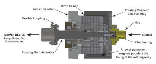
No. A novel design feature incorporating a floating shaft and a pilot bearing to center the Induction Rotor inside the Magnet Can (mounted on the motor) makes the alignment process easy. Plastic alignment spacers held in place with 4 jacking bolts (located at the 4 clock positions) keep the rotor centered at the free end of the magnet can. (See diagram below)
-
At this point, the output rotor (load) shaft is then rough aligned to the coupling flex pack hub by moving the motor up / down and side to side. When the coupling fitted bolts fit into the flex plates, the motor is tightened in place. Now the Magnet Can jack bolts can be loosened and the plastic shim spacers will be loose and can be removed – YOU ARE now aligned to within tolerance (0.010” – 0.015”). The acceptable alignment tolerance (off-set) for the coupling is 0.020”. Mis-alignment can be tolerated at even greater off-sets with substantial increases in vibration levels. (Note: the design air gap = 0.070”)